Essential Tips for Solenoid Valve Installation & Commissioning on SMT Placement Machines
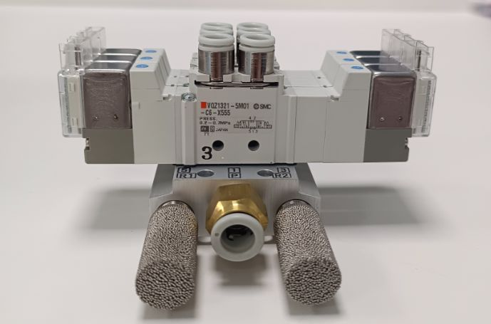
The solenoid valve is the “core switch” of the SMT placement machine’s air pressure system. Its installation and commissioning quality directly affect placement accuracy, air path stability, and even the overall production efficiency. Based on years of on-site operation experience, this article summarizes key points from pre-installation preparation to post-commissioning verification, helping you avoid common pitfalls and ensure stable operation of the solenoid valve.
I. Pre-Installation: Verify Spare Parts & Prep Environment
A good start is half the success. Adequate pre-installation work can effectively reduce early failures of the solenoid valve.
1. Secondary Calibration of Spare Part Parameters
Never rely solely on “consistent model” to confirm usability. Conduct two key tests for new valves:
- Coil resistance test: Use a multimeter to recheck. DC valves typically range from 10–30Ω, while AC valves are 50–80Ω. Deviations beyond ±5% indicate potential coil quality issues.
- Sealing & leakage test: For general valves, perform a 5-minute pressure holding test at 0.5MPa; a pressure drop ≤0.02MPa is qualified. For vacuum-specific valves, add a 3-minute holding test at -90kPa, requiring vacuum attenuation ≤5kPa.
2. Pre-Treat the Installation Environment
- Clean the valve seat mounting surface with anhydrous ethanol to remove residual sealant, dust, and oil stains, ensuring a tight fit.
- If replacing a faulty valve, inspect and replace the 10μm precision filter element in the corresponding air path. Old pipeline impurities are a major cause of new valve jamming.
II. Installation Process: Focus on Details to Avoid Hidden Risks
Installation errors are the primary cause of solenoid valve failure. Follow these standardized operations:
1. Pipeline Connection: Prevent Blockage & Leakage
- Before inserting pipelines, reverse purge them with 0.3MPa clean compressed air for 3–5 seconds to clear internal debris and avoid valve core blockage.
- Prioritize ferrule-type connections at joints (avoid PTFE tape). If sealant is needed, choosesilicone-free products (silicone contaminates nozzles) with a thickness ≤0.2mm, preventing sealant from flowing into the air path.
- For small-diameter pipelines (φ4 or below), reserve a bending radius ≥5cm to avoid increased airflow resistance due to kinking.
2. Wiring & Fixing: Ensure Safety & Reliability
- DC solenoid valves must distinguish positive and negative poles (marked “+/-” on the coil). Reverse connection leads to insufficient valve core suction. AC valves have no polarity, but ensure terminal crimping torque (0.8–1.2N·m) to prevent overheating from loose connections.
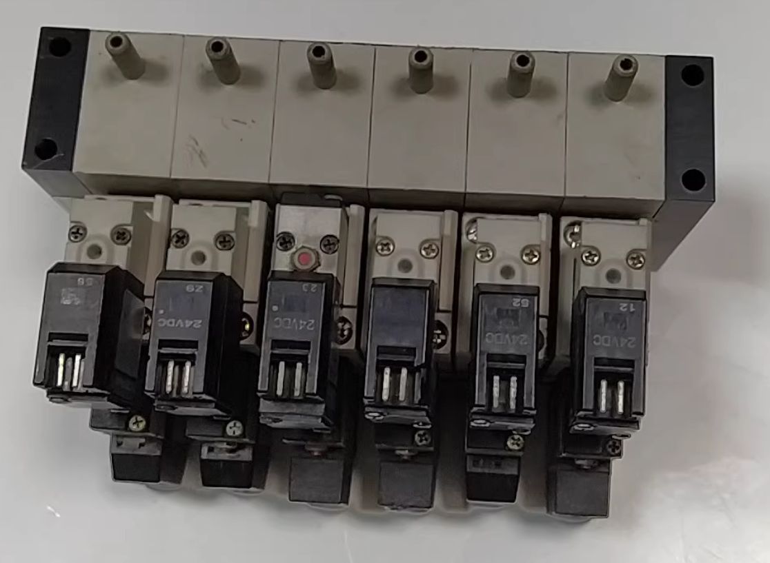
- For manifold-integrated solenoid valves, match the mounting torque to the machine model (e.g., 1.5N·m for Yamaha YSM series). Excessive torque deforms the manifold base, causing air path cross-connection.
 III. Commissioning: Layered Verification from No-Load to Interlock
Commissioning should be carried out step by step to ensure the solenoid valve matches the placement machine’s working rhythm.
1. No-Load Operation Test
- In the power-off state, manually toggle the valve core to confirm smooth commutation without jamming.
- After power-on, use a stethoscope to listen to the valve core commutation sound (crisp with no delay). Check coil temperature by hand—≤40℃ at room temperature is normal; overheating indicates coil mismatch.
2. Pressure Matching Commissioning
- Start with low-pressure air (0.2MPa) to test air path on-off, then gradually increase to the rated working pressure (0.4–0.6MPa) to avoid seal damage from high-pressure impact.
- For suction function: Measure nozzle vacuum with a gauge. It should reach -85kPa or higher within 500ms after valve actuation. If pressure build-up is slow, use an oscilloscope to check response time (≤20ms is required).
3. Interlock Timing Commissioning
In the placement machine’s engineering mode, trigger the “pick-and-place” action individually and use a high-speed camera (≥200fps) to verify synchronization:
- During pickup: Solenoid valve commutation should precede placement head descent by 0.1–0.2 seconds to pre-establish vacuum.
- During placement: Blowing action should lag behind the placement head’s PCB contact by 0.05 seconds to prevent components from being blown off.
IV. Post-Commissioning: Stability Verification & Documentation
After basic commissioning, perform a 500-cycle continuous operation test. Record vacuum degree and response time for each cycle; fluctuations exceeding ±5% indicate hidden dangers (e.g., air leakage, valve core jamming).
Finally, document key parameters (coil voltage, working pressure, test results) in the equipment maintenance log. This facilitates fault comparison and traceability in future maintenance.
Final Notes
These tips are particularly suitable for high-speed placement machines (e.g., Fuji NXT, Panasonic NPM series). For SMT production, the solenoid valve’s reliability lies in details—strictly following installation and commissioning norms can significantly reduce downtime and improve placement yield.